Start and stop position of the cam switch.
Setting the number of cam switches
Setting the hysteresis to avoid jitter effects
Synchronisation of the cam gear to the actual position by PLCMotion.
Synchronisation of the cam gear to the actual position by digital input
Stopping the cam gear byPLCMotion or fieldbus
Stopping the cam gear by digital input
Define the Action of a cam switch
How does it work?
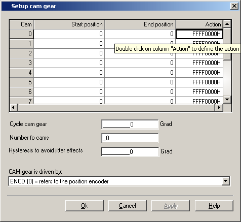
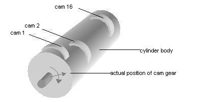
The electronic cam gear works like a mechanic cam gear . The 16 cam switches with its start and stop position can be set in any sequence. Of course, each cam switch has to be shorter than the cam cycle.
For each cam switch an action register can be defined. For e. g. by setting a flag CMx the state is transfered to a SPS. The flag status is seen by a digital output or by fieldbus. Furthermore the state of a cam can be written into a PLC-flag Mxxx and is then usable in a PLCMotion-program. The parameters for setting the cam gear are shown in the figure above.
When is the cam switch active?
Is the number of cam switches unequal to zero, the cam gear is active.
Start and stop position of the cam switch
The 16 cam switches with its start and stop position can be set in any sequence. Of course, each cam switch has to be shorter than the cam cycle.
There is no special check.
Setting the cycle:
After the defined cycle the cycle starts again. The units of the cycle are user-defined (positon control). Is there no special definition of the unit, the unit is increment (speed control). Thereby 65536 increments correspond to 1 revolution of the motor shaft.
Setting the number of cam switches
Only the defined number of cam switches is active. . Is the defined number zero, the cam gear doesn`t work.. There are 16 cam switches maximum.
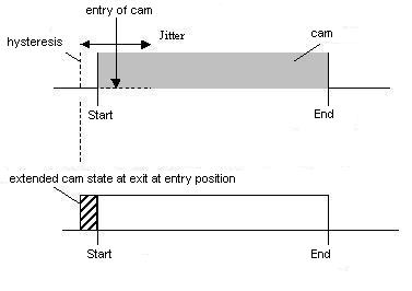
Setting the hysteresis to avoid jitter effects
To avoid jitters effects you can define a hyteresis. When reaching the cam switch position the first time, the actual position is stored. Leaving the cam switch at the same position the cam state is reset at the position plus the defined hysteresis (747-CCHYS) off set. Please pay attention, to choose the cam switch length as long as it will be necessary to detect the cam switch according to the speed of the cam gear. (Detection im 1ms-cycle).
It is not allowed to choose the hysteresis length longer than the cam switch length.
Cam gear is driven by:
There are different possibilities to select the source of the cam gear cycle:
"ENCD [0] = refers to the position encoder" := The cam gear position is driven by the position of the drive
"EGEAR [1] = refers to the master encoder " := The cam gear position is driven by the position of the master encoder
Synchronisation of the cam gear to the actual position by PLCMotion :
By a positive edge of the PLCMotion flag M75 the cam switch position will be synchronised to the actual position of the controller.
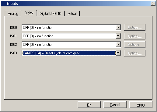
Synchronisation of the cam gear to the actual position by digital input:
By a positive edge of the digital input which is defined to "CAMRS (34) = Reset cycle of cam gear". the cam switch position will be synchronised to the actual position of the controller.
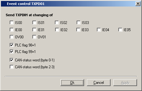
Sending of CAN telegrams
The cam gear itself doesn't send CAN telegrams. Setting the PLC flag 98 or PLC flag 99 or the virtual output OV00/OV01 you will get an interface to the can routines. Please see also
Define the Action of a cam switch
Stopping the cam gear by PLCMotion or field bus:
Is the defined number of active cam switches zero (parameter "742-CCNUM-number of cams"), the cam gear doesn't work. You can set the number of by PLCMotion and field bus.
Stopping the cam gear by digital input:
The cam gear doesn't work when the digital input which is defined to "CAMRS (34) = Reset cycle of cam gear" isn't set.
Define the Action of a cam switch
To define the action of a cam switch please double click in the column "action".