Open topic with navigation

Homing methods 7 to 10:
Method 7: Reference cam, zero pulse and positive limit switch
- The start movement is in the direction of the positive (right) hardware limit switch. It and the reference cam are inactive.
- The direction is reversed after an active reference cam. The zero corresponds to the first zero pulse after a falling edge.
- The start movement is in the direction of the negative (left) hardware limit switch. The reference point is set at the first zero pulse after a falling reference cam edge.
- The first zero pulse after overrunning the reference cam corresponds to the zero point.
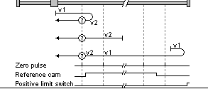
Bild: Reference cam, zero pulse and positive limit switch
Method 8:
- The zero corresponds to the first zero pulse with an active reference cam.
- At a falling reference cam edge the direction changes. The zero point corresponds to the first zero pulse after the rising edge of the reference cam.
- The direction reverses if the reference cam has been overrun. The zero corresponds to the first zero pulse after the rising edge.
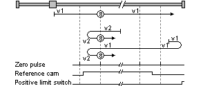
Bild: Zero point corresponds to first zero pulse
Method 9:
- The direction changes when the reference cam becomes inactive. The zero corresponds to the first zero pulse after the rising edge.
- The zero corresponds to the first zero pulse with an active reference cam.
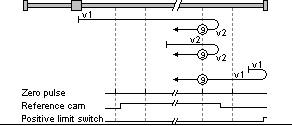
Bild: Direction changes when reference cam becomes inactive
Method 10:
- The reference cam is overrun and the first zero pulse after the falling edge corresponds to the zero point.
- After a falling reference cam edge: The first zero pulse corresponds to the zero point.
- After an active reference cam: The zero corresponds to the first zero pulse after a falling edge.
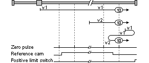
Bild: Zero pulse after falling edge corresponds to zero point.
Copyright © LTi DRiVES GmbH, Januar 2013, ID-Nr.: 0842.26B.1-00 DE