
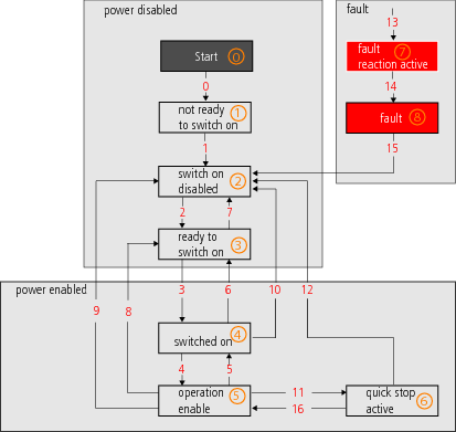
The system state of the drive is basically managed by the central state machine according to CiA402. However, the transitions and states which the state machine passes through are dependent on the drive profile setting and the bus system used. During operation, a distinction is made between drive standstill, operation, and the error states.
|
Display |
System state |
|---|---|

|
Initialization on device startup |

|
Not ready (DC link voltage possibly too low) |

|
Start inhibit (DC link voltage present, power stage off) |

|
Starting lockout |

|
Ready for start |

|
Control initialization: Autocommutation, flux build-up, etc. |

|
Control enabled |
|
|
Quick-stop active |

|
Error reaction active |

|
Error state (in this state the error is indicated directly on the display.) |

|
Device is reset (display flashes) |
|
|
Tabelle: Central state machine according to CiA 402

|
NOTE:
|

|
State number |

|
State transition |
Bild: State machine according to CANopen communication
Copyright © LTi DRiVES GmbH, Januar 2013, ID-Nr.: 0842.26B.1-00 DE
