
The wizard is used for targeted navigation through the subject areas relevant to initial commissioning. Setting the parameters correctly enables controlled movement of the drive by way of the manual mode window. For highly dynamic drive systems further settings must be made. If DriveManager 5 is opened with no project, a prompt appears asking if you want to carry out initial commissioning.
If this pop-up does not appear automatically, but you want to carry out commissioning using the wizard, you can also open the commissioning window again by clicking the pictogram or by way of the project tree. If the drive moves in an uncontrolled manner, or does not move at all, after initial commissioning, the parameter inputs must be checked.
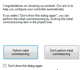
Bild: Prompt to activate wizard
The wizard helps you with the initial configuration of the controller. Work through the individual subject areas in the specified sequence. Then the motor and controller will be set up.
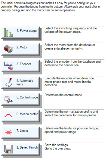
Bild: Commissioning wizard
| Subject area | Action | Instruction |
|---|---|---|

|
Set the switching frequency and the voltage supply of the power stage. | Adaptation of voltage supply to switching frequency |
|
|
Decision whether to use a synchronous motor (PSM) or an asynchronous motor (ASM). | Selection of motor |
|
|
Decision whether to use a rotary or linear motion system. | Selection of motor system |
|
|
Identification
|
Identification of motor |
|
|
|
Motor protection |

|
|
Encoder setting |

|
|
Automatic tests |

|
Open manual mode window
|
Motor test in manual mode without intervention of a higher-level PLC |

|
|
Controller setting
|

|
|
Motion profile setting |

|
Limits:
|
Define limits |

|
Scaling, IOs, field buses:
|
Set marginal conditions. For more information refer to the user manuals for the individual bus systems. |

|
Saving the settings: Create a commissioning file |
Saving: For more information on data handling refer to the Online Help in DriveManager 5 |
Tabelle: Commissioning wizard instructions
Copyright © LTi DRiVES GmbH, Januar 2013, ID-Nr.: 0842.26B.1-00 DE