
The actual position value delivered by the encoder system and the real actual position value on the axis may vary for a number of reasons. Such non-linear inaccuracies can be compensated by axis error correction (using position- and direction-dependent correction values). For this, a correction value table is filled with values for each of the two directions. The respective correction value is produced from the current axis position and the direction of movement by means of cubic, jerk-stabilized interpolation. The actual position value is adapted on the basis of the corrected table. Both tables contain 250 interpolation points.
The correction range is within the value range delimited by parameters P 0591 ENC_ACOR_PosStart "Start position" and P 0592 ENC_ACOR_PosEnd "End position correction". The start position is preset on the user side; the end position is determined on the drive side.
Possible cause of deviations
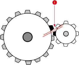
Bild: Slack between two mechanical components

|
Slack in the mechanism |
Parameters
| P. no. |
Parameter name Setting |
Function |
|---|---|---|
| P 0530 | ENC_Encoder1Se | Channel selection for the 1st encoder used |
| P 0531 | ENC_Encoder2Sel | Channel selection for the 2nd encoder used |
| P 0590 | ENC_ACOR_Sel | |
| (0) | OFF | No encoder selected |
| (1) | 1. encoder | 1st encoder selected |
| (2) | 2. encoder | 2nd encoder selected |
| P 0591 | ENC_ACOR_PosStart | Definition of correction range: The range is defined by parameters P 0591 ENC_ACOR_PosStart Start position and P 0592 ENC_ACOR_PosEnd end position. The start position is user-specified; the end position is determined on the device side from the maximum value of correction table interpolation points used and the interpolation point pitch |
| P 0592 | ENC_ACOR_PosEnd | |
| P 0593 | ENC_ACOR_PosDelta | Interpolation point pitch: The positions at which the correction interpolation points are plotted are defined via parameters P 0593 ENC_ACOR_PosDelta Interpolation point pitch and P 0591 ENC_ACOR_PosStart Start position. Between the correction interpolation points, the correction values are calculated by cubic spline interpolation. |
| P 0594 | ENC_ACOR_Val | Actual position |
| P 0595 | ENC_ACOR_VnegTab | Values of the correction table for negative direction of rotation in user units. |
| P 0596 | ENC_ACOR_VposTab | Values of the correction table for positive direction of rotation in user units. |
Vorgehensweise: Axis correction

P 0592 ENC_ACOR_PosEnd now shows the position end value of the correction range
Start control (in position control execute homing) and then move to any position.
Position control
The direction of movement is produced when the time-related change in position reference (speed pre-control value) has exceeded the amount of the standstill window in the positive or negative direction.
The direction of movement is produced when the speed reference has exceeded the amount of the standstill window in the positive or negative direction.
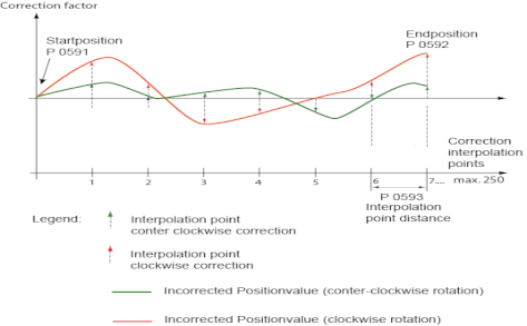
Bild: Corrected actual position value

|
NOTE: Parameterization is carried out in the selected user unit for the position as integer values. It is advisable to use the same number of correction interpolation points for the positive and negative directions. The first and last correction values in the table must be zero in order to avoid instability (step changes) of the actual position value. Differing correction values for the positive and negative directions at the same interpolation point will lead to instability in the associated actual position value when the direction is reversed, and so possibly to a step response adjustment to the reference position. |
Copyright © LTi DRiVES GmbH, Januar 2013, ID-Nr.: 0842.26B.1-00 DE