
Alongside the resolver and optical encoder standard encoder types, Hall sensors can also be evaluated. The sensor supply at pin 3 is short-circuit proof in both +5 V and 11 V operation.
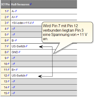
Tabelle: Pin assignment for Hall sensor evaluation
Differential track signals
Note that track signals A and B must be fed in as differential signals on X7! When using standard Hall sensors with open-collector outputs, the following adaptation circuit is recommended for each channel:
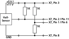
Bild: Adaptation circuit for standard Hall sensors
To use the Hall sensor, it is important to know whether the solenoids are 90° or 120° shaped. The Hall sensor function should first be executed on a scheme of a single pole pair Hall sensor with a 90° offset solenoid. The arrangement of solenoids A and B results in the states from the state table dependent on the magnetic field. They can be visualized using the scope function, producing the pattern diagram.
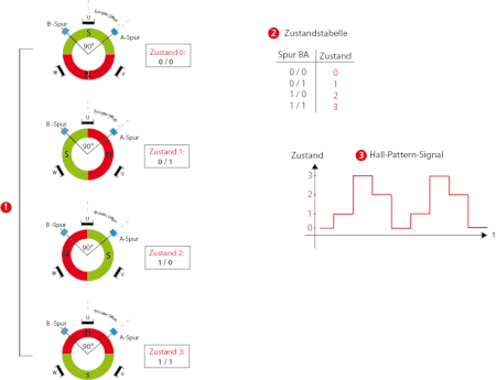
Bild: AB track of a Hall sensor with state table and pattern diagram
 The four possible states from which the offset can result.
 State table
 Hall pattern signal
Application of the Hall sensor
Vorgehensweise: Parameterizing the Hall sensor function
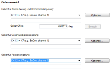
Bild: Encoder selection
Vorgehensweise: Find commutation
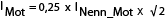
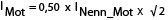

|
|
It would basically not be necessary to determine an offset if the Hall sensor is arranged orthogonally relative to the rotor. As that is not normally the case, the offset must be set manually. In manual setting in VFCON mode, the offset is set so that the electrical angle passes through zero simultaneously with the Hall pattern. If this link has been established, the offset is correctly set. To enable the motor to move without jerking even at low speeds, the PLL phase control must additionally be set so that a good overall result can be attained.
Manual determination of the offset with "VFCON"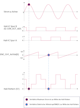
Bild: Manual offset determination
When using Hall sensors, the speed recording at low speeds is inexact. Consequently, the angle P 0500 ENC_CH1_ActVal[0] must be amplified by way of the phase control loop PLL (Phased Locked Loop) so that the sawtooth signal of the angle does not fade.
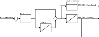
Bild: Phase control loop
Vorgehensweise: Setting for PLL
Gain factor P 0559[0] Kr_PLL
Integral-action time: P 0559[1] Tn_PLL
Angle correction: P 0612[0] ENC_CH1_HALL_EpsCorr_Sel
P 0613[0] epsMax indicates the maximum angle correction in degrees.
P 0613[1] eps1, P 0613[2] eps2 and P 0613[3] eps3 are additional correction values applied if the corresponding current
P 0614[0-3] is exceeded.
P 0614[0] currMax indicates the current in Amperes at which the maximum angle correction is to be applied. P 0614[1] curr1, P 0614[2] curr2 and P 0614[3] curr3 are the current values as from which the associated angle corrections
P 0613[0-3] epsX) are to be applied.
P 0615[0] ENC_CH1_HALL_EpsCorr_Dir permits a Hall sensor offset dependent on the direction of rotation to be set which is deducted from the encoder angle when calculating the position. Normally this value can be set to "0". For Hall sensors installed at an oblique angle this offset may be necessary however.

|
NOTE: When using Hall sensors, the speed recording at low speeds is inexact. The recommendation is therefore to set P 0745[0] MON_RefWindow to a value ≥100. If the speed signal is very noisy, it is possible to filter it via |
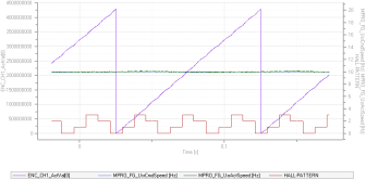
Bild: PLL gain
|
|
NOTE: With a single pole pair motor, one period of the Hall pattern signal corresponds to one mechanical revolution. |
Scope signals
| Signal number | Signal type | Signal name | Unit | Icon |
|---|---|---|---|---|
| 0004 [0] | Scope signal | current vector, comp. alpha | A | isalpha |
| 0005 [0] | Scope signal | current vector, comp. beta | A | isbeta |
| 0030 [0] | Scope signal | electrical angle of PWM and current control | pole width | epsFSM |
| 1130 [0] | Scope signal | HALL: Table index (encoder CH1) | - | HALL-PATTERN |
| 1131 [0] | Scope signal | HALL: Angle from table (encoder CH1) | - | HALL-epsVALUE |
Tabelle: Assignment of scope signals for setting of the Hall sensor
Copyright © LTi DRiVES GmbH, Januar 2013, ID-Nr.: 0842.26B.1-00 DE