
The table shows the pinning for the various encoder interfaces which can be read-in via connector X7 on the ServoOne and ServoOne junior. Column 1 specifies the interface for SinCos and TTL encoders on the ServoOne. Column 2 specifies the interface for SinCos encoders on the ServoOne junior. Column 3 specifies the interface for SSI encoders and EnDat encoders, with and without SinCos track. Column 4 specifies the interface for HIPERFACE encoders.
The selection is made via parameter P 0505 ENC_CH1_Sel = 3.
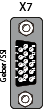
Pin assignment X7
| Pin no. |
SinCos / TTL |
SinCos for ServoOne junior |
SSI / EnDat |
HIPERFACE | |
|---|---|---|---|---|---|
Female |
1 | A- | REFCos | ||
| 2 | A+ | Cos + | |||
| 3 |
+5 V / max 250 mA |
||||
| 4 | R+ | Data + | |||
| 5 | R- | Data - | |||
| 6 | B - | REFSin | |||
| 7 | Jumper from pin 7 to pin 12 | ||||
| 8 | GND | ||||
| 9 | R- | PTC- | |||
| 10 | R+ | PTC+ | |||
| 11 | B+ | Sin + | |||
| 12 | Sense+ | Jumper from pin 12 to pin 7 | |||
| 13 | Sense- | ||||
| 14 | Clk+ | ||||
| 15 | Clk- | ||||
Tabelle: Pin assignment X7

|
ATTENTION: The pin assignment for evaluation of the zero pulse is different for the ServoOne and ServoOne junior. |

|
NOTE: You will find the pin assignment for digital Hall sensors in the Encoders < Hall sensor subject area. |
Copyright © LTi DRiVES GmbH, Januar 2013, ID-Nr.: 0842.26B.1-00 DE
