
SinCos encoders are designed as optical encoders, and meet the highest accuracy demands. They emit two sinusoidal, 90° offset signals, A and B, which are scanned by analog/digital converters. The signal periods are counted and the phase angles of signals A and B are used to calculate the rotation and count direction.
The digital time-discrete interface is based on a transfer protocol. The current positional information is transmitted from the encoder to the receiver. This may be done either serially or in parallel. As the transfer only takes place at certain times, it is a time-discrete interface. Encoders are specified in terms of their rated voltage and current consumption, and the pin assignment. Maximum permissible cable lengths are additionally specified.
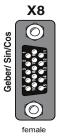
Encoder interface X8 enables evaluation of the following encoder types. For the technical specifications of the various encoder types refer to the documentation from the encoder manufacturers.
| Encoder types | |
|---|---|
|
Sin/Cos encoder with zero pulse: e.g. Heidenhain ERN1381, ROD486 |
| Heidenhain SinCos encoder with EnDat interface:
e.g. 13-bit single-turn encoder (ECN1313) and 25-bit multi-turn encoder (EQN1325) |
|
| Heidenhain encoder with purely digital EnDat interface:
e.g. 25-bit single-turn encoder and 12-bit multi-turn encoder (EQN 1337) |
|
| SinCos encoder with SSI interface:
e.g. 13-bit single-turn and 25-bit multi-turn encoders (ECN413-SSI, EQN425-SSI) |
|
| Encoder with purely digital SSI interface:
e.g. Kübler 12-bit single-turn and 12-bit multi-turn encoders (F3663.xx1x.B222) |
|
| TTL encoder with zero pulse:
e.g. Heidenhain: ROD 426, ERN 1020 |
Tabelle: Evaluatable encoder types on interface X8

|
Attention: Only one encoder with a purely digital EnDat or SSI interface can be used on connector X8 or X7. |
Parameters
| P. no. | Setting | Function |
|---|---|---|
| P 0502 | ENC_CH3_ActVal | Actual value parameter: Raw data of single-turn and multi-turn information. |
| (0) | 00...00hex | Raw data – single-turn |
| (1) | 00...00hex | Raw data – multi-turn |
| P 0507 | ENC_CH3_ Sel | Selection of encoder |
| (0) | OFF | No evaluation |
| (1) | SinCos encoder | SinCos selection |
| (2) | SSI encoder | SSI selection |
| (3) | TTL encoder | TTL selection (4) |
| (4) | EnDat 2.1/2.2 | EnDat selection |
| (5) | TTL encoder with commutation signals | HALL selection (Contact LTi DRiVES GmbH) |
| (6) | TWINsync | TWINsync selection (Contact LTi DRiVES GmbH) |
| P 0514 | ENC_CH3_Num | Numerator of encoder gearing |
| P 0515 | ENC_CH3_Denom | Denominator of encoder gearing |
| P 0570 | Absolute Position Interface select | Selector for absolute interface |
| (0) | OFF | No evaluation |
| (1) | SSI | SSI interface |
| (2) | EnDat | EnDat interface |
| P 0571 | ENC_CH3_NpTest | Zero pulse test mode |
| (0) | OFF | Not active |
| (1) | ON | Zero pulse test mode active |
| P 0572 | ENC_CH3_Lines | Setting of number of pulses (max. 65536) of TTL encoder per motor revolution: Pulses per revolution 1 - 65536 |
| P 0573 | Number of Multi Turn Bits | Number of bits of multi-turn information: Multi-turn bits 0-25 bits |
| P 0574 | Number of Single- Turn Bits | Number of bits of single-turn information: Single-turn bits 0-29 bits |
| P 0575 | ENC_CH3_Code | Selection of code with which the SSI encoder is to be evaluated. |
| (0) | BINARY (0) | Evaluation of the binary code |
| (1) | GRAY (1) | Evaluation of the gray code |
| P 0577 | ENC_CH3_EncObsMin |
Sensitivity for encoder monitoring (0-2) |
| P 0588 | ENC_CH3_EncObsAct | Amplitude of analog signal (approx. 0.75 = 1 Vss) |
| P 0630 | ENC_CH3_NominalincrementA | Setting of the increment-coded reference marks. These values are given on the encoder data sheet. Setting range 0 - 65535 |
| P 0631 | ENC_CH3_NominalincrementB |
Tabelle: Encoder interface X8
Copyright © LTi DRiVES GmbH, Januar 2013, ID-Nr.: 0842.26B.1-00 DE