
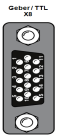
The pinout for the TTL encoder is executed in a 15-pin SUB-D connector (X8) with the following assignment:
| Connection | X8 pin no. | Assignment TTL encoder |
Assignment TTL encoder simulation |
|---|---|---|---|
Female |
1 | A- | - |
| 2 | A+ | - | |
| 3 | +5 V (+/-) 5%, Imax = 250 mA loop-controlled | - | |
| 4 | - | A+ | |
| 5 | - | A- | |
| 6 | B - | - | |
| 7 | - | R+ (zero pulse) | |
| 8 | +5 V | - | |
| 9 | R- (zero pulse) | - | |
| 10 | R+ (zero pulse) | - | |
| 11 | B+ | - | |
| 12 | - | R- (zero pulse) | |
| 13 | - | GND | |
| 14 | - | B+ | |
| 15 | - | B - |
Tabelle: Pin assignment of TTL encoder
Cable type and layout
The cable type should be chosen as specified by the motor/encoder manufacturer.
Recommended:
The following conditions must be met:
Copyright © LTi DRiVES GmbH, Januar 2013, ID-Nr.: 0842.26B.1-00 DE