
For field-oriented regulation of permanently excited synchronous machines with a purely incremental measuring system, the commutation position must be determined once when the control is started (adjustment of current rotor position to encoder zero [encoder offset]).
This procedure is executed by the "Autocommutation" function after initial enabling of the control when the mains voltage has been switched on for the first time. It can also be forced during commissioning by changing a parameter, which causes a complete controller initialization (e.g. change of autocommutation parameters, change of control mode, etc.).
Owing to the differing requirements arising from the applications, various commutation methods are provided (P 0390 CON_ICOM).
To check in commissioning whether the autocommutation has been successful, parameter P 0394 CON_ICOM_Check is provided. It comprises the current commutation angle error ActVal (1) and a parameterizable limit value Limit(0). If the commutation angle error exceeds the specified limit value, an error is generated.
In this method the rotor aligns in the direction of the injected current and thus in a defined position. The relatively large movement (up to half a rotor revolution) must be taken into consideration. This method cannot be used near end stops or limit switches! For the injected current it is advisable to use the rated current
Irated. The time should be set so that the rotor is at rest during the measurement. For control purposes, the commutation process can be recorded with the Scope function.

|
NOTE:
|
The motor shaft motion can be minimized by a shaft angle controller. The structure and parameters of the speed controller are used for the purpose. The gain can be scaled via parameter P 0391 CON_ICOM_KpScale. The precondition is a preset speed control loop. Increasing the gain results in a reduction of the motion.
An excessively high gain will result in oscillation and noise. In both methods (1) and (4), the flux forming current "Isdref" is injected as a test signal. The diagram illustrates the IECON(4) method.
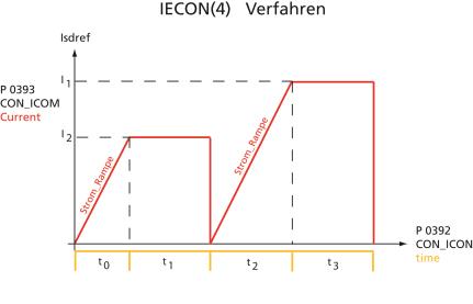
Bild: IECON(4): Minimal movement of the motor shaft
With this method, saturation effects in stator inductance are evaluated. Two test signal sequences are used for this purpose, whereby the position of the rotor axis is known after the first sequence and the direction of movement after the second. This method is suitable for determining the rotor position with braked rotors or motors with a high mass inertia.
Vorgehensweise: LHMES commutation
Test signal frequency setting:
In parameter P 0392 CON_ICOM_Time[2] the period of the test signal frequency is entered. If this value is 0, the controller uses a default test signal frequency of 100 Hz (period 10 ms). The amplitude of the test signal can be varied via parameter P 0393 CON_ICOM_Current[0]. If the value 0 is specified, the amplitude is derived from the motor rated current. If an amplitude greater than the switching frequency-dependent power stage current is specified, the amplitude is limited to half the power stage current.
The equal portion of the test signals is set via parameter P 0393 CON_ICOM_Current[1]. If this value is 0, the equal portion is determined from the motor rated current.
A simple parameter setting is obtained by specifying the value 0 for parameters
P 0392 CON_ICOM_Time[2], P 0393 CON_ICOM_Current[0] and P 0393 CON_ICOM_Current[1]. The parameters are then assigned default values which are derived from the motor/power stage current. Then the measurement is performed.
|
|
NOTE: In order to utilize the very complex LHMES autocommutation method, consultation with LTi DRiVES GmbH is required. |
Precondition:
The rotor must be firmly braked. It must not move when the rated current is applied. The stator of the machine must be iron-core. Example:
| P1503 | Direct component | 3.1 A |
| P1505 | Amplitude | 1 A |
| P1506 | Frequency of test signal | f = 333 Hz |
| P1508 | Number of periods | 50 |
Tabelle: Setting example
|
|
NOTE: It is advisable to check speed tracking error monitoring with the "Power stage off" error reaction. This monitoring feature prevents the motor from racing. |

|
ATTENTION: Parameters of the "Autocommutation" subject area may only be changed by qualified personnel. If they are set incorrectly the motor may start up in an uncontrolled manner. |
Parameters
| P. no. | Parameter name | Function |
|---|---|---|
| P 0390 | CON_ICOM | Selection of commutation variant |
| (0) | OFF (0) | No autocommutation |
| (1) | IENCC(1) | Autocommutation IENCC (1) with movement: Motor moves as far as half a rotor revolution, or half a pole pitch period (with p = 1). |
| (2) | LHMESS(2) | Autocommutation LHMES (2) with braked machine: The machine must be blocked by a suitable brake during autocommutation. The occurring torques and forces may attain the rated torque and force of the machine. Apply the method only in consultation with LTi DRiVES GmbH. |
| (3) | IECSC(3) | - |
| (4) | IECON(4) | Autocommutation IECON (4) with minimized movement: Here, too, the rotor must be able to move. However, an appropriate parameter setting can reduce the rotor motion to a few degrees/mm. |
| (5) | HALLS(5) | - |
| (6) | HALLSdigital(6) |
Digital Hall sensor |
| P 0394 | CON_ICOM_Check | Check whether commutation was successful. |
| (0) | Limit(0) | Limit value for maximum commutation angle error |
| (1) | ActVal(1) | Current commutation angle error |
Tabelle: Autocommutation parameters
Copyright © LTi DRiVES GmbH, Januar 2013, ID-Nr.: 0842.26B.1-00 DE