
The speed controller is executed as a PI controller. The gain (P-component) and the integral-action time (I-component) of the individual controllers are programmable.
In order to optimize the speed control loop, two rectangular reference steps are preset.
For automatic controller optimization the step response and transfer function wizards are available.
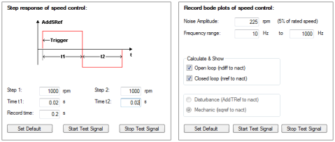
Bild: Advanced analysis of the speed controller
Vorgehensweise: Optimizing the speed controller
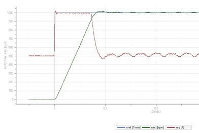
Bild: Step response to rated speed
Creating the transfer function
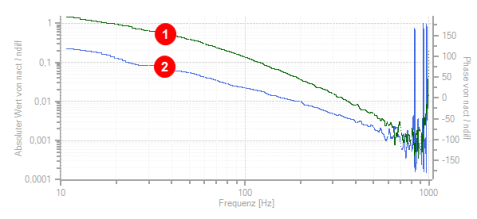
The oscilloscope automatically records the amount and phase response of the controller according to the controller settings. This produces an initial estimate of the control quality.
To determine the transfer function the noise amplitude (motor rated current) and the sampling time (default 0.125 ms) must be specified. Click the "Start Test Signal" button.
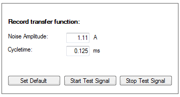
Bild: Noise amplitude, sampling time

|
Green curve = Amount Y-axis left = Absolute value of nact/ndiff |

|
Blue curve = Phase response Y-axis right = Phase response nact/ndiff |
Bild: Speed controller transfer function
Copyright © LTi DRiVES GmbH, Januar 2013, ID-Nr.: 0842.26B.1-00 DE