
To filter any noise on the actual speed value, or to damp resonance frequencies, various filter combinations can be used. A range of filter variants are available. The coefficients of the transfer function are automatically determined as soon as the values for the middle and limit frequency and the width have been entered.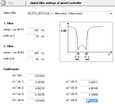
Bild: Selection of various digital filters
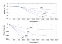
| Bode diagrams PT1 to PT4 | Phase response |
|---|---|
|

|
Bild: Bode diagrams PT1 to PT4
Parameters
Tabelle: Parameters to set the filter constants
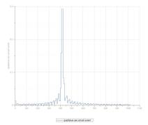
Vorgehensweise: FFT signal analysis
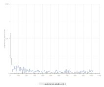
| FFT without filtering | FFT with filtering |
|---|---|
|
|
Tabelle: FFT transformation

|
NOTE: Note that the filters not only have an effect on the amount but also on the phase of the frequency response. At lower frequencies higher-order filters (PT3, PT4) should not be used, as the phase within the control bandwidth is negatively influenced. The coefficients can also be specified directly via parameter P 0327 CON_SCON_FilterPara. They take effect directly, so changing them is only recommended when the control is switched off. |
|
|
NOTE: A large bandwidth results in less attenuation of the limit frequency. |
Copyright © LTi DRiVES GmbH, Januar 2013, ID-Nr.: 0842.26B.1-00 DE