
A servocontroller works on the principle of field-oriented regulation. In the motor the current is injected so that the magnetic flux is at the maximum and a maximum torque can be generated on the motor shaft or on the carriage of a linear motor.
The closed-loop control is cascaded. The position, speed and current controllers are configured in sequence. The sequence of controller setup must always be observed in controller optimization.
1. Current controller setup
2. Speed controller setup
3. Position controller setup/pre-control
The overall structure of the control loops is set out in the control loop schematic.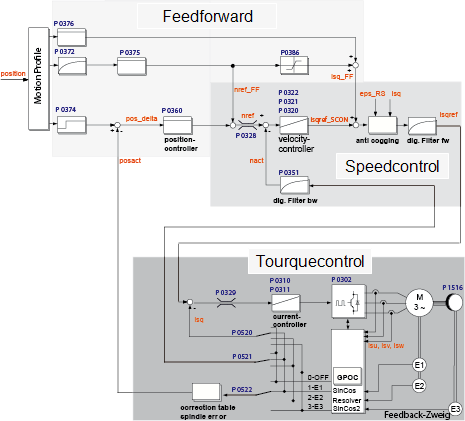
Bild: Closed-loop control schematic
Sampling times of the individual control loops (switching frequency 8 kHz)
Specified features of a well configured control:
Setting
When using a LTi DRiVES GmbH standard motor data set, the control parameters are preset for the specific motor model (external mass inertia = motor inertia). If using third-party motors, a manual setting must be made for the drive by way of the motor identification or by calculation in order to define the appropriate control parameters for the motor model.
Speed control loop:
The setting of the speed controller with the associated filters is dependent on the motor parameters (moment of inertia, torque/force constant, load inertia/mass, friction, rigidity of the connection and encoder quality). Consequently, a manual or automatic optimization is often required.
Position control loop
The position control loop is dependent on the dynamism of the underlying speed controller, on the setpoint (reference) type and on the jerk, acceleration and interpolation methods.
Copyright © LTi DRiVES GmbH, Januar 2013, ID-Nr.: 0842.26B.1-00 DE